Thursday, December 4, 2014

Day 25 Last ->Laboratory Experiments of inductor, capacitor, and resistor; Teacher demo of Various V and I vs time graphs with the change of inductor or capacitor or delta frequency. Transformer, Useful Chart>


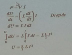
Shown calculation steps for frequency for Irms and wattage.

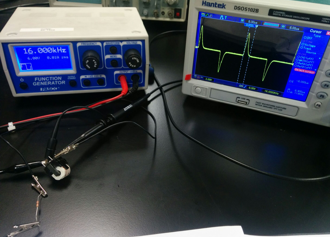
Setup all connected in series of RLC circuit 

Setup calculation with ending a percent error analysis.


2 measurement separately for different circuit first RLC.

5000 and 5 second setting for frequency and time frame
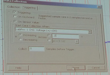
 More setup dialog checks

Result of series inductor circuit
Capacitor linked in circuit
Capacitor connected in series detected by Logger Pro


Both conductor capacitor and inductor shown red is inductor and blue is capacitor.


Change decrease frequency by 10 hertz inductance go down for inductor circuit. and Result of changing 60-10hz amplitude goes down by equation 1/2 XL=1/2/pi/f


10 hertz below amplitude go up


Inductor 16 hertz

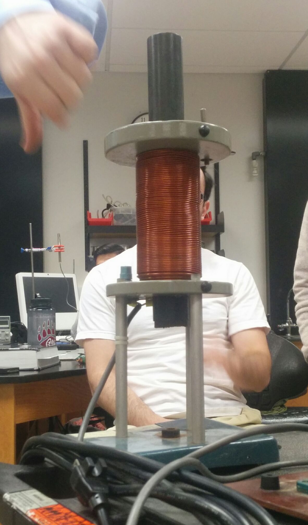
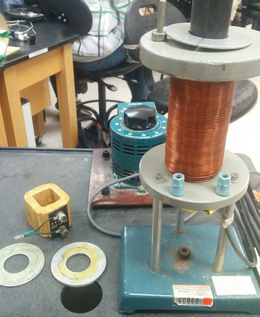
Transformer experiment
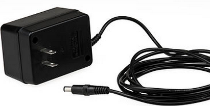
Outside of Wall Wart


A wall wart(AC adapter) was passed around the class for examination of eddy currents (undesired) and electrodynamical transformations of energy.    A transformer is made of two inductors linked together by an iron core(best if laminated). The iron core manipulates the magnetic flux from one inductor to the other. Eddy currents are the undesired currents created by the changing magnetic field. The Eddy currents increases energy lost and the solution to this is to laminate the plates of the iron core because laminated layer reduces the size of the induced loop and therefore reduces the amount of energy lost. 

Useful Chart
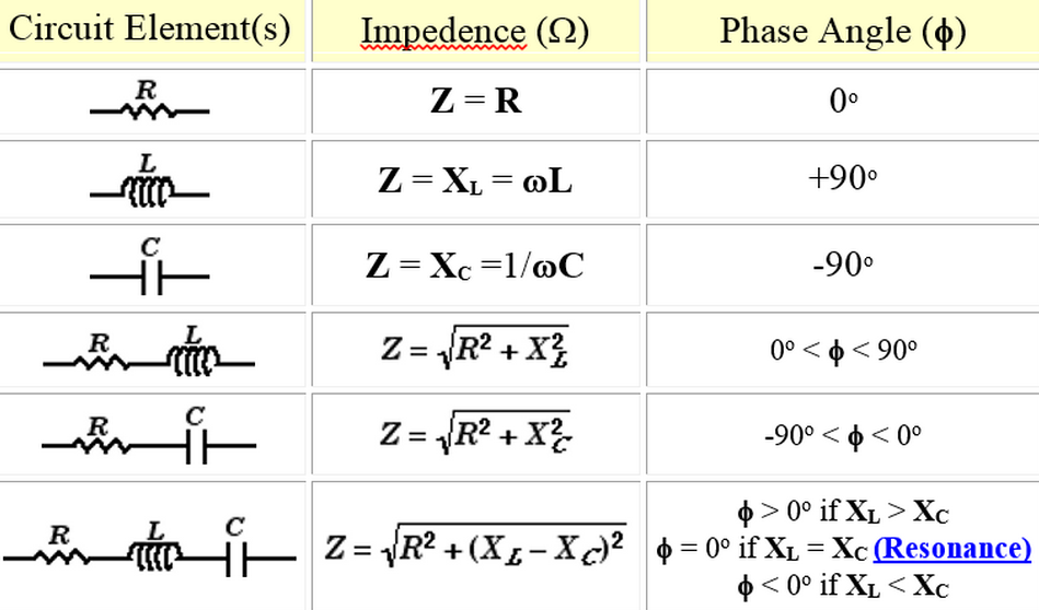
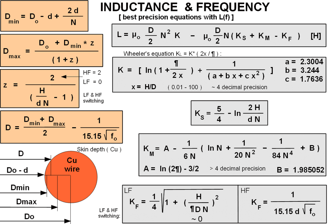
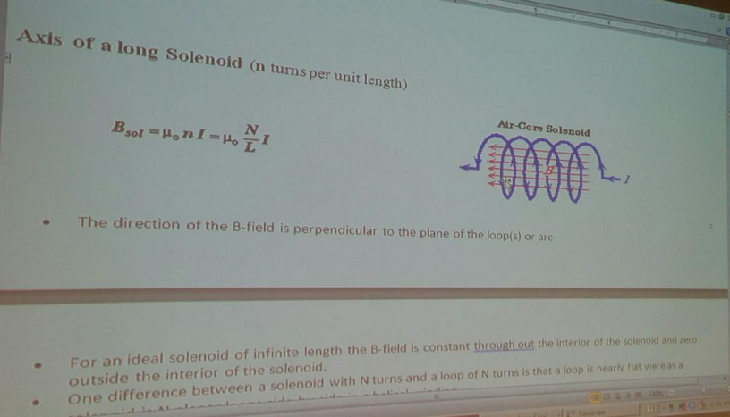
List of equations relative to impedance(R) and phase angles with Resistor, Inductor, and capacitor: with RL, RC, RLC circuit. 

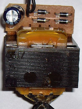
Transformer is made up 2 conductors made up of 2 conductors iron cores
Hook it up alternating voltage->current -> field 
coil reversing 60hz and magnetic field up and down
Magnetize iron core: turn it to U magnet 

Tuesday, December 2, 2014

Day 24 ->Alternating Circuits and Phase change of sinusoidal waves, Lab resistor V, I vs time, and V vs I graphs

Alternating Circuits and Phase change of sinusoidal waves.
Alternating Currents and Voltages graph


First result of percent error of resistor
Percent error of resistor using Vmax and logger pro probes. 


Result of solving percent error of resistor using formulas and derived recombined formulas
First result of the percent error of resistor 
Graphs of Voltage vs time, Current vs time, and Potential vs Current


List of formulas used to solve frequency frequency, Irms, and efficiency
Laboratory procedure for inductor with AC input source


Data and calculation for inductor with and without core
Analysis of alternating circuits

The AC RC circuits
For last part of lab, RC circuit powered by AC was closed with capacitor and resistor both connected to function generator. The multimeter was the measurement device and voltimeter and current meter both connected to the Logger Pro. The total resistance within circuit is the Total impedance, Z value. By using formula Z can be listed and derived as below equations.
Equations derived for Z values

Thursday, November 27, 2014

Day 23 ->Energy in wires monitor example, Inductance: ActivPhysics, Oscilloscope, solonoid, magnetic field interference, laboratory questions


Energy in wires monitor example


Back of monitor is leg there is a choke
Inductance equations derived and constants used along with it.

Energy I capacitor is i/2 cv'2 is similar to inductor
1/2 Li'2
P=VI
integration of derived energy as shown here derived and shown as LI^2=U which is similar to kinetic energy.
Energy is store every is turned on and it will be changing with change of time

Rc circuit Simulation picture circuit calculating the current
Current is 2 amps answer from V/ohm=>  V=IR I=V/R

Faraday's law of induction. the reason for Faraday's

Website answer Active Physics questions

A fist test square wave and measuring decay of inductor with 150 ohm resistor
Testing wave

Measuring human wave frequency
5 ms per division 3 peaks on screen 10 across 1/18*10'-3 60 hz. Basically picking the ac current

Measure inductor voltage inductor voltage
Setup of the good function generator showing the Vmax and used to find Imax and frequency from the Scilloscope.
Cursor pulse width and cursor pulse rate 8
5.4 ms divide for the value of tau.
These pictures are showing Inductors with time changing current
White board representation of inductor graph from previous Oscilloscope result.
Lastly, a circuit was built containing hooked up to a function generator, a resistor, and an inductor. In addition, a voltmeter was used in order to find the voltage across the resistor and inductor. The equations of uncertainty and answers are shown below for the measurements of inductance

Tuesday, November 18, 2014

Day22 ->Currents in wire, Magnetic Sensor setup and Faraday's law experiment,Tesla's Wardenclyffe tower, Inductor differentiation, Phenomenon #2: experiment with tubes of conductive and nonconductive material when magnet is dropped inside

55 number of coil per unit length

Currents in wire. Force
If direction is reversed they repel each other  from the force vector

Force coulomb derived for ampere

Magnetic field Faraday s law experiment
Through hall effect sensor.
Hall effect sensor 
Sensor vertical then rotate it in the vertical Line
Measure magnetic field of 1. 5. 10. 20. loops of wire test tube with 3 volts.
Magnetic field
Make magnetic field bigger then you can overlapping them. Magnetic field due to solenoid
Imagine loop of wire thumb give direction  magnetic field of. Show

Area vector be cos theta

Result of Faraday's 10 year frustrating experiment comes jerking iron rod for the awesome discovery of electromagnetism pertaining to this experiment is the induction.  
Faraday question magnetic. Question Electricity from magnetism. Prof Mason showed class the analog galvanometer with which follows the formula below and shows that faster the iron core moves,the more the galvanometer can detect more current.
Thus introduced the rolls of wire in the inductor.
Changing magnetic field is called induction.

Figure out 4 different things about experiment produce maximum current from inductor coil
  Increased current to strengthen of magnetic field. 
  Faster speed means larger current
  Increase coils of wires
  Overlay coils of wires
  Decrease size of loop
Diagram for galvanometer


For example when showing a bigger loop, and unsurprisingly the less amperage with ammeter was detected when iron rod jerked in and out inside the bigger loop. 


Unit analysis of Tesla
Break unit B(magnetic flux) to fundamental units
Tesla is N/m/A

Variec 120ac to lower power to levitation coil b/c current flowing to show and adjust how high the metal ring can levitate


Mag coil up that magnetic field create current in ring creates a magnetic field going down
Split ring show nothing
Laminated ring up so much(due to reduced eddy current, with more efficiency)
Magnetic field Induced current light bulb show (light up with higher inductance)
Pickup coil or driving coil
Tesla's Wardenclyffe tower
The tower (400kilohertz and the higher it gets, more efficient it isequation below), very similar to inductor and modern inductive charging except the troubles are that it uses Earth as conductor(unknown electrostatic changes globally(environmental issues)) and problem how to charge people with electricity fees.

Tesla's Wardenclyffe tower

First thought the ring and coil interaction from induced current and current repelling each other.


Motional Emf explained

Overall E=vB
vBL=motion emf
Approach 180 degree opposite degrees
Useful equations derived for application of magnetic flux.

Magnetic field from angle as a function of x
Inductor differentiation
Below are a list of inductor to the right more inductance.

Formula for inductance


Phenomenon #2: experiment with tubes of conductive and nonconductive material when magnet is dropped inside

Pic of solenoid depiction


Representation of the electric field vector of a wave of circularly polarized electromagnetic solenoid presentation during radiation which is similar to this experiment except with wires.

Calculation and presentation of how the magnet inside tube would fall.
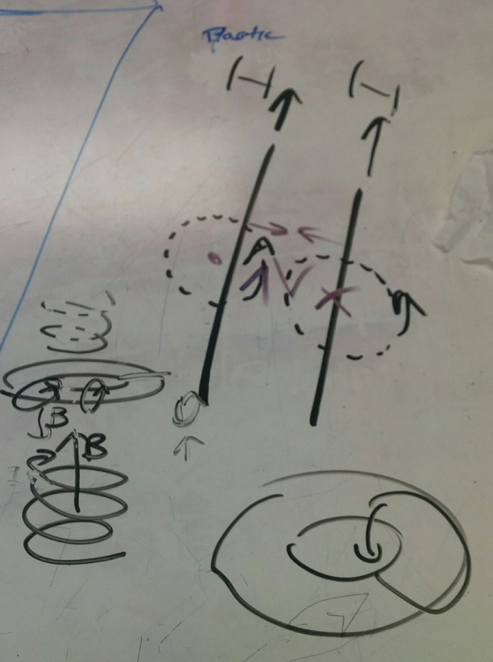
Drop through both tube it will be slower in aluminum and normal speed in acrylic